

Every concrete shell is built slightly wrong. What matters is where, by how much, and whether the structural analysis knows.
For most structures, small geometric deviation is a finishing problem. For a thin shell, it is a structural one. The shell carries load through its shape, so a change in shape is a change in how it carries load. Two pieces of work, one from 2025 and one from 2026, take that seriously. One builds a shell over a clay mound and feeds its scanned surface back into the analysis. The other measures how printing error forms, and shows that the repeatable part of it can be designed out before anything is made.
A shell is only as good as its worst patch
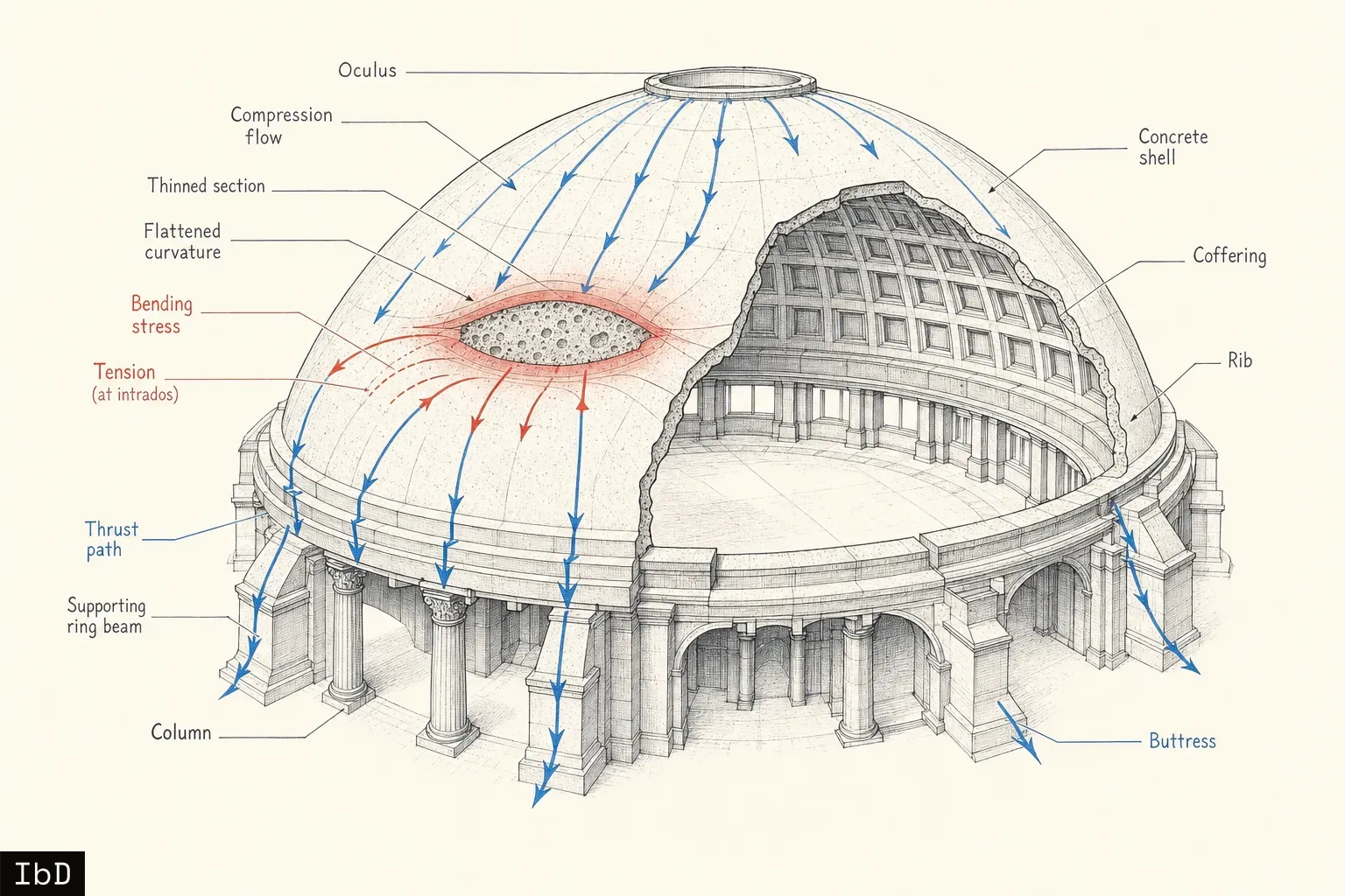
Thin shells are famously sensitive to imperfection. Their buckling capacity can fall well below the value calculated for the perfect geometry, and the shortfall depends on the form and location of the imperfection as much as its size.
That makes the usual measure of construction accuracy, average surface deviation, a weak one. A shell that is uniformly a few millimetres off can behave almost exactly as designed. A shell that is accurate almost everywhere, with one patch where the curvature has flattened, the section has thinned or the curvature reverses, can concentrate bending in the region the form-finding was meant to protect. A support that has landed in the wrong place can change the force flow through the whole surface. The deviations that matter are local, and they are specific to the structure.
A clay mound and a scanner
A team at the University of Bath built a concrete shell in a way that is at once very old and very new. The formwork was a shaped mound of clay, cheap, reusable and easy to sculpt. Concrete was sprayed over it, reinforced with a hybrid of textile and steel. Augmented reality guided the placement of the clay, the formwork and the reinforcement, so the crew could see the digital geometry overlaid on the physical work.
Then the finished surface was scanned, and the measured imperfections went back into the structural analysis. The shell was checked as built, not as drawn.
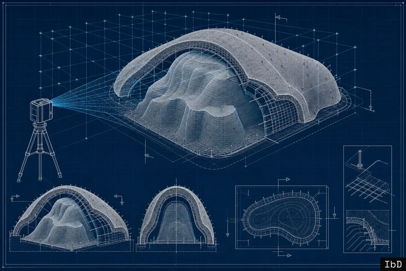
The work was presented as a peer-reviewed IABSE conference paper in August 2025, backed by the physical prototype, tests on sprayed-concrete samples, a point-cloud survey and a structural assessment. The authors are clear about the limits: the clay's moisture has to be controlled and the clay has to be extracted afterwards; the underside finish depends on the mould; spraying brings rebound and shadowing behind reinforcement; scans need careful datum control; durability and waterproofing at joints remain open; and none of this is a standardised production method yet.
The loop matters more than the mould
The clay is charming and the augmented reality is impressive, but neither is the part that transfers. The transferable part is the loop: design, build, measure and then verify against the measurement.
That loop needs only a few things to work. A single geometry thread has to run from the parametric model through analysis, set-out and scanning to a deviation map, so the scan can be compared with the design in the same coordinates. The quantities that come back from the scan have to be structural ones: curvature, thickness, support position. And the analysis has to be able to take the measured geometry, or imperfection cases derived from it, as input.
This is the part of the recent work I find most quietly radical. A point cloud used to be documentation, filed after the job to prove it was done. Here it becomes part of the structural check.
Repeatable error can be designed out
The second piece of work comes from a different process entirely. A preprint from BAM, posted in May 2026, studied powder-bed printing, where a binder or water is dosed voxel by voxel into a bed of dry material. Using high-resolution stereophotogrammetry, the team measured how small changes in water dosage produced systematic swelling, rounded edges and error that depended on direction.
Because the errors were systematic, they could be predicted. The team pre-distorted the CAD model to cancel them out, so the printed part came out closer to the intended geometry.
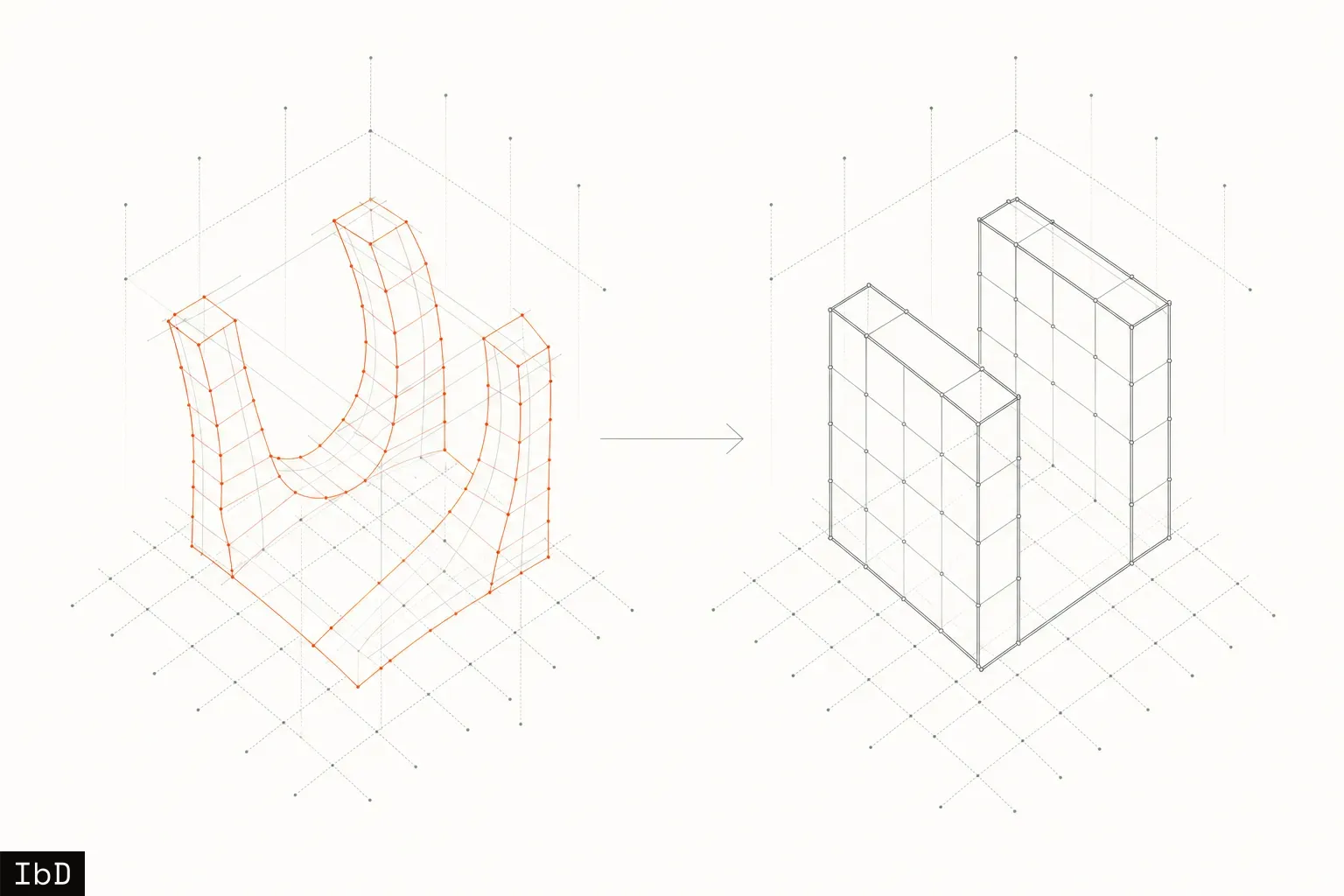
The most telling result was in the mechanical tests. Across the tested range, geometry changed materially while stiffness and strength barely moved. The material was robust. The shape was not. For most printed elements, that is reassuring. For a shell, where shape carries the load, it is a warning: geometry is the first thing to drift, and the property that matters most.
The limits are worth stating. Powder-bed behaviour does not transfer directly to sprayed or fabric-cast concrete. And compensation only works on repeatable error. It cannot correct porosity, weak lifts, inadequate cover or the random deviations of a real site.
Tolerance should come from the analysis
Put the two together and a clearer picture of construction accuracy emerges. Some error is systematic and repeatable, and can be measured once and compensated in the design. Some error is random, and has to be accepted within limits. The question is what those limits should be.
For a shell, the answer cannot come from a generic finishing standard. It has to come from the structure: the minimum thickness the analysis can tolerate, the local curvature below which bending demand rises sharply, the support positions beyond which the force flow changes. Those numbers are specific to each shell, and they can only be set by running the analysis with deliberate imperfections and seeing where it breaks.
That turns tolerance from a site instruction into a design output, and the scan into the test that checks it.
In most structures, geometry describes where the structure is. In a shell, geometry is the structure. It deserves to be measured like one.
References
- Design, construction and analysis of a concrete shell using clay formwork (University of Bath research record, IABSE conference paper, August 2025)
- Water-driven geometric uncertainty in powder-bed printing (BAM preprint, May 2026)