
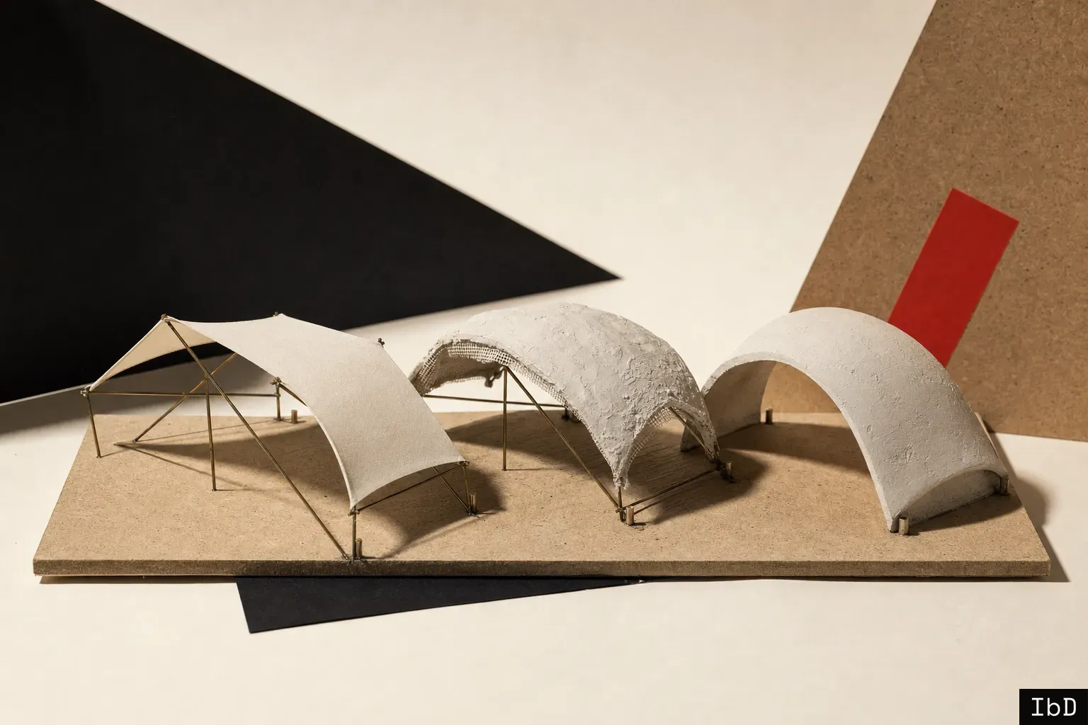
A thin concrete shell is drawn as one shape and built as three. The fabric, the wet concrete and the cured shell each settle into their own equilibrium, and usually only the last one gets designed.
That gap is where most of the interesting shell research of the past two years sits. Very little of it is about a new shape. Almost all of it is about the distance between the shape on the screen and the structure that turns up on site, and about the steps in between that decide which one you get. Much of it is still numerical, and some of it broke on the way to the lab floor. That is what makes it worth following: the field is experimenting in the open.
The drawing describes only the final state
Form-finding is usually framed as a single problem: find the geometry that carries its own weight in compression, with as little bending as possible. Solve it well and the shell can be astonishingly thin.
A shell cast on a flexible formwork has to pass through at least two earlier states to reach that geometry. First there is a prestressed membrane, empty, held in tension by its edges and supports. Then there is the same membrane carrying wet concrete, sagging and shifting under a load that arrives in passes rather than all at once. Only after curing does the compression shell exist.
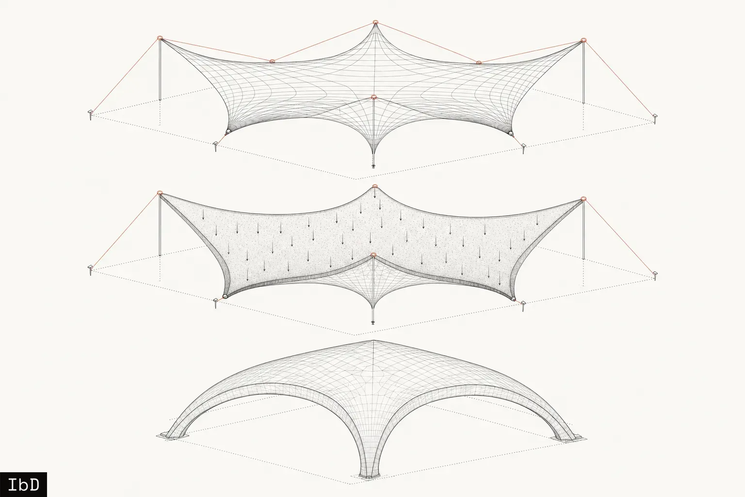
Each state has its own equilibrium. A geometry optimized for the cured shell alone says nothing about whether the fabric can hold that shape under tension, or whether the wet load will pull it somewhere else on the way. Whatever bending was optimized out of the final state can quietly reappear in the earlier ones, as sag, as local flattening, or as curvature that reverses where it should not.
The more promising form-finding methods now treat this as a coupled problem. A paper from the Technical University of Munich, presented at the IASS symposium in September 2026, optimizes a single shared topology so that it sits in nearly the same position as both a tensioned membrane and a self-weight compression shell, using force densities of opposite sign to reconcile the two. Free edges emerge as funicular arches without being imposed. It remains numerical, and the wet state is still missing, but the direction is right: the formwork and the shell are designed as one object. Of everything here, it is the method I most want to see tested in fabric and concrete.
The historical masters already worked this way. Isler found his shells by hanging cloth and inverting it. Candela chose hyperbolic paraboloids partly because they could be formed with straight timber boards. The shape was always a consequence of how it could be made. What has changed is that the coupling can now be computed instead of intuited.
The shell is weakest before it exists
The cured shell is rarely the structure that fails first. The temporary structure that makes it fails first.
A prototype published this year in the International Journal of Space Structures made this plain. A multi-axis robot deposited concrete along non-planar, force-informed paths over elastically bent timber strips, with scanning registering the deformed substrate and a staged finite-element model tracking early-age stiffening. The formwork carried roughly 500 kg of fresh concrete. Then the boundary bolts tore out after the third of five planned layers. The team published the failure in full, which is rarer and more useful than another clean result.
Nothing about that failure was exotic. It was a connection detail under a transient, unbalanced load that would not exist once the shell had cured. It is exactly the kind of load that a design focused on the final state never checks.
The sequence of application is a load case. Where material goes first, how long each pass waits before the next, and how the wet mass distributes across a flexible support all produce forces that the finished shell never sees. Those forces can govern.
The material is changing just as fast. Fresh concrete gains cohesion and stiffness over minutes, and its behaviour in the first hour or two decides whether a layer stands, slumps or buckles. A preprint from BAM and TU Eindhoven treats elastic buckling and plastic collapse as two limits of one process, and it has reproduced the collapse of a printed wall to within a single layer. A 28-day cube strength describes a material that does not yet exist while the shell is at its most vulnerable.
The built shell is a different shell
Every shell on site deviates from its drawing. The question is whether the deviation matters structurally, and that question can now be answered rather than assumed.
Scanning used to be documentation: a point cloud filed after handover to show the job was done. In the more rigorous recent work it has become an input. A team at the University of Bath formed a sprayed concrete shell over a shaped clay mound, guided placement with augmented reality, scanned the finished surface, and fed the measured imperfections back into the structural analysis. It is a low-tech mould with a high-rigour loop around it, and the loop from scan to analysis is the real advance.
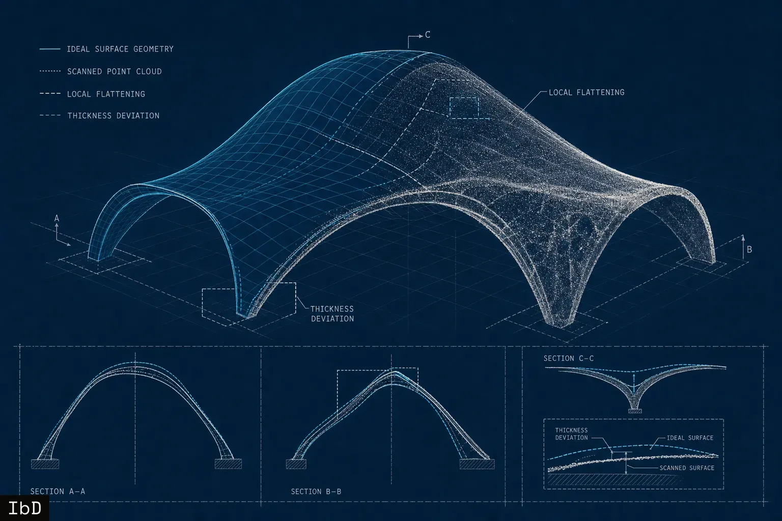
What the scan reveals also changes what tolerance should mean. Average surface deviation is a weak measure for a shell. A few millimetres of uniform error can be harmless, while a local patch of flattened curvature or a strip of thin section can concentrate bending in exactly the region the form-finding was meant to protect. Tolerances worth specifying are structural ones: minimum thickness, local curvature, support position. They come from the analysis, not from a generic finishing standard.
Laboratory work at BAM on powder-bed printing points the same way. Small changes in water dosage produced systematic swelling and edge rounding that stereophotogrammetry could measure and a pre-distorted model could compensate, while stiffness and strength barely moved. Geometry was the first thing to drift. It was also the easiest thing to correct, once it was measured.
Steel and approval follow the making
Reinforcement is usually drawn for the finished structure and then forced into whatever process builds it. The strongest built evidence of the past two years reverses that order.
Tor Alva, the 30 m printed concrete tower that ETH Zurich built in the Swiss village of Mulegns, organized its reinforcement around deposition. Horizontal steel rings were placed during printing. Longitudinal bars went in afterwards, threaded through digitally formed channels and locked with self-compacting mortar. Directional testing addressed the weakness along layer joints. The system is specific to columns and nowhere near a shell solution, but the principle carries: channels, laps and rings are designed with the making, not added after it.
Approval works the same way. Conventional concrete standards assume compaction, formwork and a homogeneous material, and layered or unconventional processes break all three assumptions. A 2025 review in RILEM Technical Letters maps where those standards fall short and concludes that qualification has to cover the complete workflow, from geometry and reinforcement position to material behaviour over time, interruptions, curing and inspection records. Approval is still granted project by project. The unit being qualified is a process, not a mix.
The loop is the technology
Taken together, the work describes one idea. The thin shell worth building comes out of a closed loop: equilibrium-driven geometry across every state the structure passes through, construction stages treated as load cases, material behaviour measured while it is still changing, the built geometry captured and fed back into verification, and reinforcement and qualification designed around the actual process.
Robots, printers and augmented reality can automate parts of that loop. None of them replaces it. A printer depositing concrete onto a geometry that was only ever optimized for its final state carries the same blind spots as a crew with a spray gun, only faster.
This is why the research holds my attention. I came to shells through formwork, and in 2015 patented a formwork approach for thin concrete shells. From that side of the problem it was always clear that the formwork was not a support for the design. It was part of the design. The work coming out now gives that intuition a method: it can be modelled, measured, and checked against what was actually built.
None of it is settled. The methods are young, the prototypes are small, and some of them failed. That is the exciting part. The questions are open enough that every carefully cast and carefully measured shell adds something to the answer.
The interesting question in shells is no longer how thin the structure can be. It is how faithfully each state can be carried into the next.
A shell is drawn once and built three times. The work is making those four agree.
References
- Coupled membrane-shell form-finding (IASS-IWSS 2026, mediaTUM): https://mediatum.ub.tum.de/1863548
- Physics-informed generative design of funicular shells (arXiv preprint, 2026): https://arxiv.org/abs/2604.16621
- CAD-integrated isogeometric thin-shell workflow (IASS-IWSS 2026): https://pub-12d7216700584ed7a1b50eac1448d179.r2.dev/IASS_2026_-_IWSS_2026_paper_28.pdf
- Conformal printing on bending-active timber formwork (International Journal of Space Structures, 2026): https://doi.org/10.1177/09560599261460824
- Fresh-concrete buildability model (BAM / TU Eindhoven preprint, 2026): https://arxiv.org/abs/2609.07679
- Clay-mound formwork with scan-informed analysis (University of Bath, 2025): https://researchportal.bath.ac.uk/en/publications/design-construction-and-analysis-of-a-concrete-shell-using-clay-f/
- Geometric uncertainty in powder-bed printing (BAM preprint, 2026): https://arxiv.org/abs/2605.18290
- Tor Alva reinforcement and testing (ETH Zurich, 2025): https://baug.ethz.ch/en/news-and-events/news/2025/04/setting-new-standards-for-3d-printed-concrete-construction.html
- Standardization aspects of concrete 3D printing (RILEM Technical Letters, 2025): https://letters.rilem.net/index.php/rilem/article/view/201